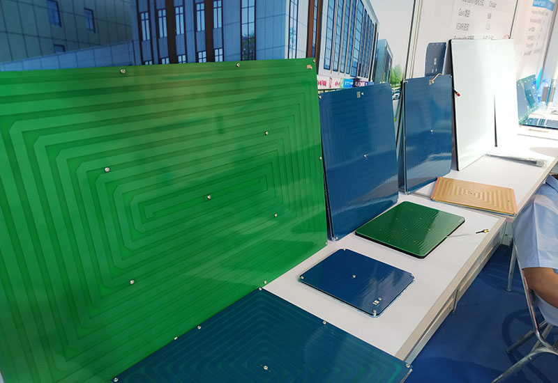
How to Choose the Right UHF RFID Antennas for your Application?
Abstract
The white paper discusses the main parameters of UHF RFID Antennas, and how they affect the operation. It can help you select the right UHF RFID antenna step by step to match your application.
What is UHF RFID and how it works
Ultra-high frequency (UHF) is the ITU designation for radio frequencies in the range between 300 megahertz (MHz) and 3 gigahertz (GHz). The wavelengths corresponding to these limit frequencies are 1 meter and 10 centimeters.
RFID stands for Radio Frequency Identification, which is widely used to identify and track the objects by attached tags automatically. It uses electromagnetic waves to read and extract the information stored in the chip of tags.
Usually, the typical UHF RFID system mainly consists of three parts: a fixed RFID reader, an UHF RFID antenna and a passive RFID tag. The reader is used to receive & send the RF signal to/from the antenna, decodes and interprets the data in the tag. While the antenna is adopted to pick up the radio waves that generated by the tag and send it to the reader which decodes the waves as digital information. The tag chip contains memory which stores the product’s electronic product code (EPC) and other variable information so that it can be read and tracked by RFID readers at any time anywhere.
How to choose the frequency range of UHF RFID antennas
The primary frequency ranges include 433MHz, 865-868MHz, 902-928MHz as well as 860-960MHz for UHF RFID System.
As it’s known to all, due to regional regulations, the frequency bands for UHF RFID slightly differ for the US, Europe and other regions all over the world. Most UHF RFID antennas are specified between 860 to 960 MHz. While the two main common operation frequency ranges are FCC( Federal Communication Commission) and ETSI (European Telecommunications Standards Institute). FCC operates at 902-928MHz and ETSI operates at 865-868MHz. Most of the regions and countries follow either standard in the industry in the rest of the world.
What’s the exact read range of UHF RFID antennas
With a passive UHF RFID system, it is very difficult to accurately measure the read range. It significantly depends on the RFID IC (integrated circuit) sensitivity, RF power output level of the reader and the gain of the antenna. Technically, the higher the power the farther the read range and vice versa. Furthermore, the more sensitive the IC, the further the read range. Supposing it’s permanent for the IC sensitivity and power output level, however, the read ranges have something crucial with the gain of the antenna. The higher the gain, the farther the read range and vice versa.
What’s more, there are a couple of factors which have something significant to do with the read range, such as cable length and environmental factors, etc. In order to minimize the effect, various kinds of interference tests should be carried out to match the UHF RFID system well.
At Weibonuo Technologies, we offer a wide range of UHF RFID antennas. The read range is range from 5 feet to 50 feet (15m) or higher based on the normal output power ≤1 watt (30dBm). Typically, the read range of 8dBi circular polarization is about 6m and 12-15m for 12dBi linear polarity RFID antenna. Furthermore, the read range of the linear antenna is a little farther than a circular antenna based on the same gain and size.
How to choose the gain of the UHF RFID antenna
The gain has defined the ratio of power generated by the antenna to radiate more or less in any direction compared to a hypothetical lossless isotropic antenna. It has something significant to do with the read range and half-power beamwidth. The higher the gain, the longer the range and the narrower the beamwidth or vice versa. What’s more, the antenna gain mainly depends on the size of the antenna. The bigger the size, the higher the gain and vice versa.
RF signal is always lost when it passes through cables and connectors. The longer the antenna cable or pigtail, the more the signal loss. A higher antenna gain is necessary to compensate for these losses to meet the required read range. General speaking, the RF range will be reduced by half for every 6 dB signal loss. The lost signal has to be compensated by choosing a proper antenna gain. If more gain is necessary, choose a higher gain antenna depending on your system requirement. The below shows the signal loss across cables and connections.
The value of the signal loss is about -5.6dB with 50ft (15.2m) LMR195 and -2.0dB with 50 ft LMR400 for 866/915MHz RFID Antenna. It’s 0.5dB for both N-type connectors and RP-SMA series for 866/915MHz RFID antennas. Lower cost, longer range. Higher loss, shorter range.
At Weibonuo Technologies, there are three common series of UHF RFID antennas. One is a low gain (5/6dBi) series, another is middle gain (8/9dBi) series and the last high gain (11/12dBi ) series. However, some specific custom antennas can reach as high as 15dBi with ultra-narrow beamwidth. Select the suitable antenna gain based on the shape of your interrogation zone and coverage needs.
How to choose the polarization of UHF RFID antenna
Normally, the most common forms of polarization used are linear polarization and circular polarization for UHF RFID Antennas. There are two forms for the linear polarity. One is vertical, where the electric field is perpendicular to the Earth’s surface. The other is horizontal, where the electric field is parallel to the Earth’s surface. While there are two directions of propagation that comes with circular polarization: Right-Hand-Circular-Polarized(RHCP) which follows a clockwise pattern, and Left-Hand-Circular-Polarized (LHCP) which follows a counterclockwise pattern. In most cases, RHCP is more widely used for a wide range of applications.
Technically speaking, the polarization of the UHF RFID antenna has to be consistent with the orientation of the tag that is placed. The linear polarized antenna should be used if the tags need to be read on the same plane and aligned with the plane of the antenna. That’s to say, the polarization of antenna has to be horizontal/vertical if the identified tag is horizontal/vertical oriented. In most cases, the circular polarization antenna should be used if the tag orientation is not something that will be reliable or consistent.
For this reason, there are a couple of advantages for circular polarization compared with linear polarization for UHF RFID antennas.
Firstly, the Faraday effect deals with the interaction between light and magnetic fields. It affects linear, but not circular, polarized signals, and the effects are more severe at lower frequencies. Secondly, circular polarization is more resistant to signal degradation due to atmospheric conditions. Thirdly, it’s much easier and faster to install the circular polarity antenna because the linear-polarized antenna has to be aimed in the exact correct direction. At last, the circular polarity antenna is much more reliable since there is a low risk of misalignment and encountering interference.
How to choose the connector/port type for UHF RFID antennas
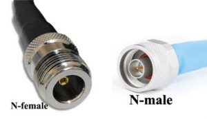
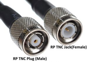
It depends on the interface of the UHF reader. Usually, there are three common families of connectors below for the UHF RFID antennas. One is N series, which includes N-female and N-male. The second is SMA families which include SMA-female, SMA-male, RP SMA-female, and RP SMA-male. The last is TNC families that consist of TNC female, TNC male, RP TNC Plug and RP TNC Jack.
N-Type
SMA Type

RP TNC
How to connect the UHF RFID antennas to the reader
Normally, there are two common ways of the connection interface for the UHF RFID antenna. One is fixed on the backplate with flanged connectors which can be mounted on the plate. The other is with a certain length coaxial cable and comes out from the backplate of antenna or the side of antenna radome. A pigtail/jumper cable is necessary for the first type because both reader and antenna need to be connected. Usually, the pigtail includes two connectors and a certain length of cable. One end is connected to the reader and the other to the antenna. In most cases, the low loss cable LMR series such as LMR195/LMR240/LMR400 is strongly recommended.
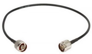
There is no need for the second one because the length of the coaxial cable can be customized. The recommended cable models are RG series, xD-FB series and SYV series and so on.
How to choose the mounting bracket for UHF RFID antennas
The mounting type depends on your specific applications. However, there are two most common mounting options. One is wall mount for indoor and the other mast/pole mount for outdoor. The mounting accessories are quite simple for the wall mount. Usually, it includes the below mounting screws.
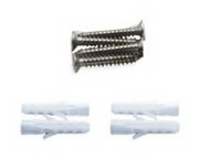
As to mast/pole mount, at Weibonuo Technologies, there is a wide range of mounting brackets for various kinds of antenna and poles below.
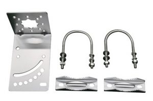
Firstly, the most common style is a light-duty which includes one L bracket, two each U bolts and clamps as well as 304 stainless steel screws & washers. It’s widely used for low and middle gain UHF RFID antennas. However, it’s not adjustable except up and down.
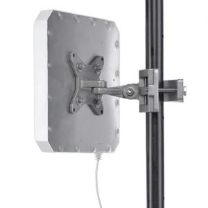
Secondly, it’s the heavy-duty style which consists of four parts which are all die-casting aluminum. The extremely robust design is especially suitable for industrial applications. Usually, it’s used for higher gain UHF RFID Antenna with a big size such as 12dBi or 15dBi gain.
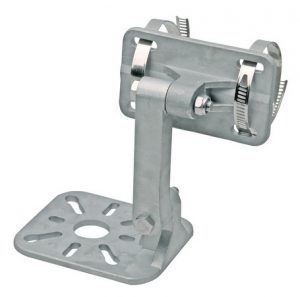
At last, it’s a universal mounting bracket that is suitable for most UHF RFID antennas and mounting options, which includes mast mount and wall mount. It ‘s easy to mount with UDLR (up, down, left and right) adjustable clamp and tilts. There is no limit for the diameter of the mounting mast/pole. It ranges from 38mm to 100mm or bigger with optional 304 stainless steel adjustable clamps.
What’s more, sometimes the mounting brackets are not necessary because the antenna can be embedded in the enclosure box. In this case, there is no need to use any mounting bracket at all.
How to choose the Ruggedness of UHF RFID Antennas
For outdoor applications, the operation of UHF RFID antennas mainly depends on the materials and IP rating, which varies a lot in different environments.
For example, the antenna radome must be rugged enough to absorb the impact of high-speed rocks when it’s installed on the rails. In this case, the key is the material and thickness for the antenna radome. To save cost, the fiberglass is widely used for the UHF RFID radome in rugged environments such as the extreme cold or hot weather conditions. While in rainy areas, the IP rating must be IP65 at least for RFID antenna. The maximum wind velocity and service life must be taken into consideration in coastal circumstances.
At Weibonuo Technologies, there is a wide range of UHF RFID antennas with different designs, materials and IP ratings that can be suitable for different environments and all-weather operation. The normal radome materials range from fiberglass, UV-ABS to PC as well as ASA. The IP rating includes IP54, IP55, IP65, and IP67 for both indoor and outdoor. As a matter of fact, they can be customized in specific applications for all-weather operation.
10 Warning Tips For the Installation of the UHF RFID Antennas.
1. Under some conditions, this antenna may not prevent electrocution. Users should keep the antenna away from any overhead wires. If antenna contacts a power line, any initial protection could fail at any time. IF ANTENNA NEARS ANY OVERHEAD WIRES, IMMEDIATELY LET GO, STAY AWAY, AND CALL UTILITY COMPANY.
2. THIS ANTENNA IS DESIGNED TO BE INSTALLED ONLY BY A TRAINED PROFESSIONAL INSTALLER. Select a safe site to install the antenna.
3. The distance between any power lines and the installation site should be at least one and one-half times the height of the antenna and mast assembly. Make the distance even greater, if at all possible. Since all overhead power lines look somewhat alike, consider them all dangerous and stay well away from them.
4. NEVER work alone; always have someone near who can summon help.
5. Check weather conditions. Be sure that the area is not slippery and make sure that rain or thunderstorms are not predicted for the day you install the antenna.
6. The wind can blow the antenna into a nearby power line. Don’t install, adjust or move antennas in moderate or heavy winds.
7. If you need to use a ladder, make sure it is made of non-conductive (non-metallic) material
8. If the antenna or any part such as the wire or mast comes in contact with power wires DO NOT TOUCH IT OR ATTEMPT TO MOVE IT. Contact the power company for assistance.
9. Antennas improperly installed or installed to an inadequate structure are susceptible to wind damage that can be very serious or even life-threatening. Ensure that the installation is properly grounded according to the National Electrical Code. Ensure that the antenna is properly secured and structurally sound to support all loads (weight, wind & ice) and properly sealed against leaks.
10. Protect the antenna connection with the correct vulcanizing rubberized tape.
